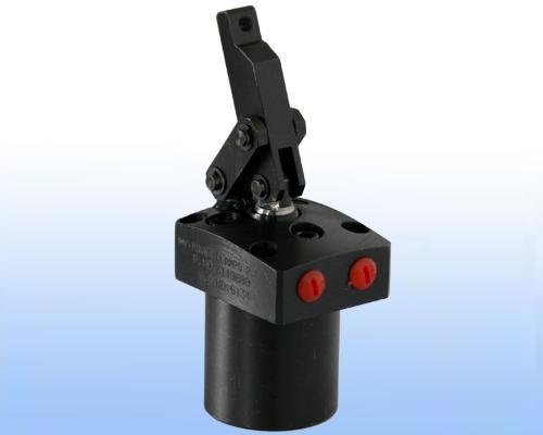
Vertical Swing Cylinder
Vertical swing cylinders are used in applications similar to that of swing cylinders and can replace swing cylinders in many places. In the unclamped position, the work piece area is free from the strap, to facilitate easy loading / unloading. It is a double acting cylinder. The job gets clamped in the piston push direction. The clamping strap is connected to the piston by a linkage mechanism.
Installation of the cylinder is very simple with 4 cap screws on the top flange. For threaded port cylinders clamp and de-clamp ports are provided on face of the mounting flange as shown in figure. For manifold port cylinders clamp and de-clamp ports are provided on bottom face of the mounting flange as shown in respective figure.
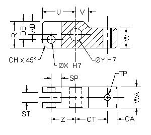
| BORE | PART NO. | U | V | AB | DB | R | W | SP | ST | Z | CT | CA | WA | TP | X | Y | CH | WEIGHT |
|---|---|---|---|---|---|---|---|---|---|---|---|---|---|---|---|---|---|---|
| 25 | 3204400 | 24.3 | 16.5 | 6.5 | 10 | 16 | 8 | 12 | 6 | 18.5 | 23.5 | 6 | 11.8 | M6 | 6 | 6 | 4 | 0.15 kg |
| 32 | 3201700 | 32 | 13 | 13 | 18 | 26 | 18 | 11 | 10.1 | 24 | 28 | 14 | 22 | M6 | 8 | 12 | 5 | 0.2 kg |
| 40 | 3200500 | 40 | 15 | 16 | 22 | 32 | 24 | 12.5 | 12.1 | 30 | 38 | 12 | 26 | M10 | 10 | 15 | 6 | 0.4 kg |
| 50 | 3206300 | 45.5 | - | 13 | 13 | 26 | 26 | 17.5 | 16 | 32 | 42 | 12 | 32 | M12 | 12 | 12 | 5 | 0.5 kg |
| 63 | 3203400 | 64 | 20 | 24 | 32 | 48 | 38 | 20.5 | 20.1 | 48 | 65 | 13 | 38 | M16 | 16 | 22 | 10 | 1.0 kg |
| 80 | 3211100 | 69 | - | 21 | 21 | 42 | 42 | 25 | 20 | 48 | 66 | 14 | 42 | M16 | 16 | 22 | 10 | 1.2 kg |
All dimensions are in mm, Overall dimension tolerance ± 0.5 mm.
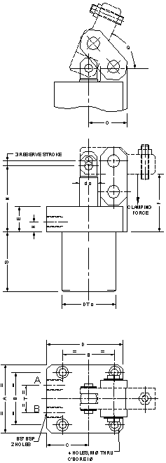
| PART NO. WITH THREADED PORT | 3110801 | 3111801 | 3111601 | 3111201 | 3111901 | 3112201 |
|---|---|---|---|---|---|---|
| Clamping Force (@ 150 bar) | 5.7 kN | 10.3 kN | 14.8 kN | 22.4 kN | 34.5 kN | 54.8 kN |
| Ø BORE | 25 | 32 | 40 | 50 | 63 | 80 |
| PORTS | 2 | 2 | 2 | 2 | 2 | 2 |
| A | 51 | 70 | 82 | 90 | 112 | 134 |
| D | 68 | 82 | 93 | 105 | 125 | 155 |
| B | 40 | 55 | 63 | 70 | 85 | 100 |
| C | 40.5 | 47 | 52 | 60 | 69 | 88 |
| F | 51 | 62 | 69 | 78 | 97 | 118 |
| T | 22 | 30 | 35 | 35 | 42 | 48 |
| d | 14 | 18 | 22 | 30 | 38 | 45 |
| E | 28 | 28 | 30 | 30 | 38 | 48 |
| H | 17 | 17 | 17 | 17 | 19 | 19 |
| N | 57 | 70 | 79 | 91 | 113 | 139 |
| S | 47 | 60 | 72 | 80 | 102 | 115 |
| DT | 48 | 55 | 65 | 80 | 95 | 118 |
| O | 25.5 | 37 | 46 | 45 | 72 | 69 |
| Q | 71° | 72° | 67.4° | 72° | 87° | 82° |
| BS | 1/8" | 1/8" | 1/4" | 1/4" | 3/8" | 3/8" |
| M | 5.5 | 6.6 | 9 | 9 | 13.5 | 14 |
| I | 9.5 | 11 | 14.5 | 14.5 | 20 | 20 |
| STROKE ±1 | 23.5 | 30 | 38 | 40 | 55 | 65 |
| OIL VOL push | 12 cc | 24 cc | 45 cc | 78 cc | 171 cc | 328 cc |
| OIL VOL pull | 8 cc | 16 cc | 31 cc | 50 cc | 115 cc | 223 cc |
| WEIGHT | 1.5 kg | 2.5 kg | 4 kg | - | 11 kg | - |
| STD. STRAP | 3204400 | 3201700 | 3200500 | 3206300 | 3203400 | 3211100 |
* Force is specified at 150 bar.
Cylinder part no is without strap, strap to be ordered separately.
Manifold mounting cylinder drawing details are given below.
All dimensions are in mm, Overall dimension tolerance ± 0.5 mm.
Subject to change for improvement. (Revision - August 13).
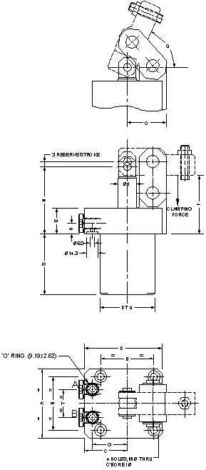
| PART NO. WITH MANIFOLD MOUNTING | 3111701 | 3111000 | 3110900 | 3111200 | 3112100 | 3112200 |
|---|---|---|---|---|---|---|
| Clamping Force (@ 150 bar) | 5.7 kN | 10.3 kN | 14.8 kN | 22.4 kN | 34.5 kN | 54.8 kN |
| Ø BORE | 25 | 32 | 40 | 50 | 63 | 80 |
| PORTS | 2 | 2 | 2 | 2 | 2 | 2 |
| A | 51 | 70 | 82 | 90 | 112 | 134 |
| D | 68 | 82 | 93 | 105 | 125 | 155 |
| B | 40 | 55 | 63 | 70 | 85 | 100 |
| C | 40.5 | 47 | 52 | 60 | 69 | 88 |
| F | 51 | 62 | 69 | 78 | 97 | 118 |
| T | 22 | 30 | 35 | 35 | 42 | 48 |
| d | 14 | 18 | 22 | 30 | 38 | 45 |
| E | 28 | 28 | 30 | 30 | 38 | 48 |
| H | 17 | 17 | 17 | 17 | 19 | 19 |
| N | 57 | 70 | 79 | 91 | 113 | 139 |
| S | 47 | 60 | 72 | 80 | 102 | 115 |
| DT | 48 | 55 | 65 | 80 | 95 | 118 |
| O | 25.5 | 37 | 46 | 45 | 72 | 69 |
| Q | 71° | 72° | 67.4° | 72° | 87° | 82° |
| BS | 1/8" | 1/8" | 1/4" | 1/4" | 3/8" | 3/8" |
| M | 5.5 | 6.6 | 9 | 9 | 13.5 | 14 |
| I | 9.5 | 11 | 14.5 | 14.5 | 20 | 20 |
| G | 25 | 35 | 40 | 48 | 55 | 70 |
| STROKE ±1 | 23.5 | 30 | 38 | 40 | 55 | 65 |
| OIL VOL push | 12 cc | 24 cc | 45 cc | 78 cc | 171 cc | 328 cc |
| OIL VOL pull | 8 cc | 16 cc | 31 cc | 50 cc | 115 cc | 223 cc |
| WEIGHT | 1.5 kg | 2.5 kg | 4 kg | - | 11 kg | - |
| STD. STRAP | 3204400 | 3201700 | 3200500 | 3206300 | 3203400 | 3211100 |
* Force is specified at 150 bar.
Cylinder part no is without strap, strap to be ordered separately.
Manifold mounting cylinder drawing details are given below.
All dimensions are in mm, Overall dimension tolerance ± 0.5 mm.
Subject to change for improvement. (Revision - August 13).