Hydraulic Coupling Unit

  • Home
  • Hydraulic Coupling Unit

Hydraulic Coupling Unit

Description :

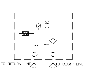
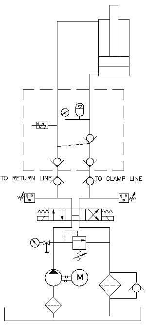
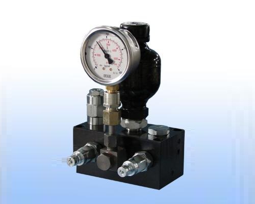
Hydraulic coupling units are used whenever the fixture is separated from the pressure generator, e.g. in flexible manufacturing systems. This fully equipped coupling unit has been developed for manual coupling and uncoupling for the purpose of clamping and unclamping. This unit includes two quick disconnect coupling (QDC) to connect / disconnect 'Hydraulic Power Unit', Pilot operated check valve to hold pressure in clamping line, Accumulator to compensate leakage (if any) in clamp line, Glycerin filled pressure gauge , Built in single acting cylinder takes care of across piston leakage and avoid building pressure in return line.

Versions :

  • For Double Acting Elements : Part No. 4500137
  • For Single Acting Elements : Part No. 4500155

Installation :

This unit is mounted on pallet which is moving and live hydraulics is not continously available

Specifications of Coupling Unit :

Minimum Operating Pressure 50 bar
Maximum Operating Pressure 250 bar
Accumulator Charging Pressure 80% of Operating Pressure
Accumulator Volume 75 cc
Total Cylinder Volume 500 cc
Specifications of Power Unit :
Power Unit Hydraulic Power Unit with Control Panel
Pump Output 1.8 LPM
Motor 3 Phase, 1 HP
Tank Capacity Approximately 30 Litres
Useful Oil Volume Approximately 25 Litres

Power Unit Hydraulic Circuit :

This unit should have direction control valve, which is double solenoid, spring centered, and center open. At center position pressure line is connected to tank line and motor is unloaded. Due to this one can connect / disconnect quick disconnect coupling at center position. Push buttons are provided on pendent for ease of operation.
Sequence of Operation :

A) Clamping
  • Connect the Quick Disconnect Coupling (QDC), if not already connected.
  • Press the Clamp button.
  • Hydraulic pressure builds up and the Ready for Disconnection (Green) indicator glows.
  • Disconnect the QDC and fit the dust caps.
  • The job remains securely clamped and the pallet is ready for movement.
B) Unclamping
  • Remove the dust caps and clean the Quick Disconnect Coupling.
  • Connect the QDC in the unpressurized condition.
  • Ensure the Ready for Connection / Disconnection indicator is ON.
  • Press the Unclamp button.
  • All hydraulic elements retract and the pressure gauge returns to zero.
  • The Ready for Disconnection indicator glows.
  • The workpiece can now be removed and a new job loaded.

Notes :

  • Clamping and unclamping time is more because every time accumulator is charged and discharged.
  • Accumulator is to support small leakages. Accumulator charging pressure should be approximately 80% of operating pressure. If operating pressure is reduced below Accumulator charging pressure, then there will not be any oil output for leakage compensation. This is unsafe situation. If cylinder oil volume is more than 500 cc, then one must use bigger accumulator.
  • In conventional clamping, live hydraulic line is always connected. Pump output can make-up leakages and Pressure switch can give signal for low or no pressure and machine can be stopped. Both options are not possible for moving pallet, hence one should critically check that leakage is nil or negligible.
  • Single Acting Cylinder. - This for absorbing across piston leakage in decoupled condition. Due to check valves in QDC unclamp line is in trapped condition. Due to this cylinder oil pressure does not rise in return / unclamp side of cylinder. (In normal on line clamping unclamp line is always connected to tank line. To have clamping force first condition is to have clamping pressure in clamp line and secondly there should not be any pressure in unclamp line.) Here accumulator take care of maintaining pressure in clamp line and small single acting cylinder take care of keeping unclamp line in unpressurised mode in decoupled condition. When cylinders are new and do not have any leakage, this cylinder does not have any function. After some months there may be small across piston leakage, it will be supported by accumulator, and this leaked oil to other side will get absorbed by this cylinder.
  • In the absence of this cylinder, the following are two conditions:
    • If you are using push action to clamp the job, due to across piston leakage oil will get trapped in unclamp side due to check valve in QDC. Pressure will rise there. Instead of job, oil will get clamped, and job can move due to cutting forces.
    • If you are using pull direction to clamp the job, due to across piston leakage and check valve in QDC, piston will start moving up to unclamp the job. You will get full pressure on gauge due to accumulator support, but job will be in unclamped condition. This is very hazardous condition for machine and operator as we do not have any feed back of unclamped job.

Preventive Checking Procedure:

  • Clamp the job as per defined procedure and disconnect QDC.
  • After 8-24 hours check following points.
    • Pressure drop is not more than 20 bar.
    • Built in cylinder piston should not come out by more than 8 mm.

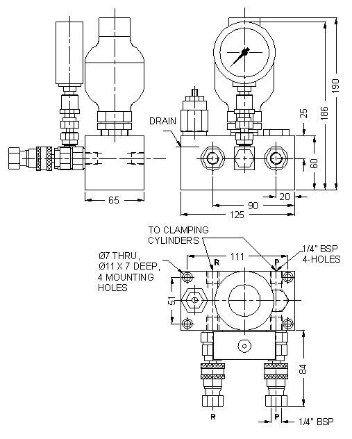
Dimensional details :