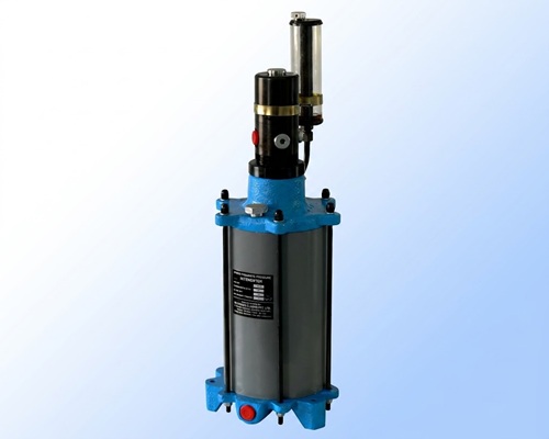
Hydropneumatic Intensifier Single Acting
Hydropneumatic intensifiers are widely used on conventional machines, where hydraulic power unit is not available with the machine. Single acting elements are generally used with hydropneumatic intensifiers..
In the static condition, (Pressure x Area) at air side is equal to (Pressure x Area) at oil side. Hydropneumatic intensifier has one oil cylinder and one air cylinder. The pistons of both these cylinders are connected to each other. In single acting intensifier, the air cylinder is single acting, spring return. The air piston is the driving piston and the oil piston is the driven piston.
When air is allowed in the intensifier by a D.C. valve, oil on the hydraulic side gets pressurized and is forced out. The oil output operates the clamping cylinders and the job gets clamped. After releasing the air pressure, due to the spring in the intensifier, the air piston returns back and the job gets declamped. Oil is pushed back into the intensifier due the spring in the cylinder.
This is an important feature of hydropneumatic intensifier. The oil- side of the hydropneumatic intensifier, hydraulic hoses and cylinders form a close loop system. Oil in this loop is a confined fluid. There must be a leakage compensation for the confined oil, if there is any leakage (across piston of cylinder and through connectors). The make-up oil system compensates for leakage by adding small volume of oil at every stroke. In the unpressurised mode, make-up oil is always connected to the oil side. In the pressurization stroke, as the piston moves up and crosses the high pressure seal, the make-up oil gets disconnected from the oil side. In case of leakage, when the system pressure is released after operation, the hydraulic piston moves down to the bottom. When it crosses the high pressure seal, the make-up oil gets connected to the oil side. Any leaked-out volume causes vacuum on the oil side and is automatically compensated due to the atmospheric pressure.
Please see "More About Hydropneumatic System" and Bleeding and Trouble Shooting of Closeed loop system".
For 5 to 7 bar air pressure, select an intensification ratio of 28 so as to get about 150 bar hydraulic output. For 3.5 to 4 bar air pressure, select an intensification ratio of 40 to get about 150 bar hydraulic output.
Oil volume for every cylinder is given in the catalogue. Sum up all the oil volumes of the cylinders to get the total oil requirement. Intensifier output must be more than the total oil volume required. e.g. To use 2 cylinders of part no. 1510200 and 2 cylinders of part no. 1540100 for clamping a job, Oil required = (oil volume of 1510200) x 2 + (oil volume of 1540100) x 2 = (22 x 2) + (34 x 2) = 112 cc Select the part no. 1128200 with 200 cc oil output.
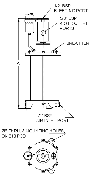
| PART NO. | INTENSIFICATION RATIO | A | OIL OUTPUT | AIR VOLUME PER STROKE | WEIGHT |
|---|---|---|---|---|---|
| 1115100 | 1:15 | 560 | 200 cc | 3 lit | 22 kg |
| 1115200 | 1:15 | 875 | 400 cc | 6 lit | 28 kg |
| 1128100 | 1:28 | 560 | 100 cc | 3 lit | 22 kg |
| 1128200 | 1:28 | 875 | 200 cc | 6 lit | 28 kg |
| 1140100 | 1:40 | 560 | 75 cc | 3 lit | 22 kg |
| 1140200 | 1:40 | 875 | 150 cc | 6 lit | 28 kg |
* Maximum air inlet pressure 7 bar.
All dimensions are in mm, Overall dimension tolerance ± 0.5 mm.
Subject to change for improvement. (Revision - July12)