Pneumatic Swing Cylinder

  • Home
  • Pneumatic Swing Cylinder

Pneumatic Swing Cylinder

Description :

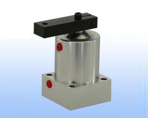
Pneumatic swing cylinders are used for clamping in the sheet metal industry and for light machining applications. In the unclamped position, the work piece area is free from the strap, for easy loading / unloading. These are pull type cylinders. The piston rotates by 90° during the swing stroke, followed by straight clamping stroke.

Versions :

Swing direction (while clamping and viewed from the rod side):

  • CW – Clockwise
  • CCW – Counter Clockwise

Specifications :

Bore Diameter 50 mm
Maximum Air Pressure 6 bar
Minimum Air Pressure 2.5 bar
Clamping Force 1 kN at 6 bar Air Pressure

Notes

  • To avoid damage to the swing mechanism, hold the clamping strap in a vice while tightening or loosening the clamping strap nut.
  • To prevent damage to the swing mechanism due to impact, use a flow control valve at both ports.
  • Clamp the workpiece only during the straight clamping stroke.
  • Do not exceed the standard strap length.
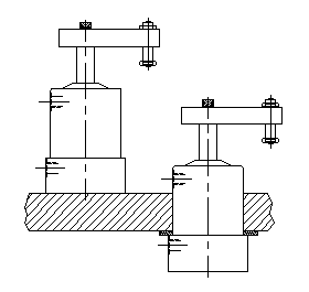
  • For height adjustment, use either a spacer at the mounting plate or an adjusting bolt on the strap, as shown in the figure.
  • Use only dry and lubricated air.
  • For ordering the seal kit, add the prefix "S" to the part number.
  • For non-standard cylinder requirements, please contact us at sales@hypowerclamps.com.

Dimensional Details :

TYPE PART NO. WITH STRAP
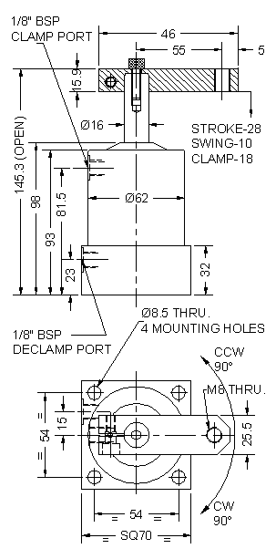
CW 4710500
CCW 4710600

All dimensions are in mm, Overall dimension tolerance ± 0.5 mm.

Subject to change for improvement. (Revision - July12).
Application Example :

pneumatic swing cylinder application